
Current electricity is a very important topic in Physics and there are multiple concepts that will be discussed in this topic such as:
- Electric current
- Conventional current
- Electromotive force
- Potential difference
- Ohm’s law (ohmic and non-ohmic conductors)
- Resistance
Therefore, there are a lot of concepts that you should know about this topic. So, let’s start from the very beginning without further introductions.
Current electricity
The definition of electric current?
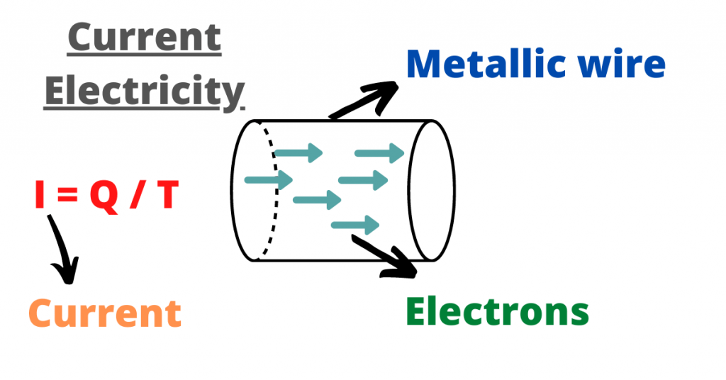
The electric current is the movement (flow) of electrons from a conducting path. In other words, when electrons flow, an electric current is produced.
Let me recall the electrons are the subatomic particles that move around the nucleus of an atom.
Electrons are negatively charged and they have no substructure or components and elections are very small if compared to the nucleus of an atom.
Fun Fact: Electrons were discovered after protons (subatomic particles with a positive charge).
The purpose of giving the above information is to explain that electric current is the movement or stream of electric charge in a circuit.
To understand this in a better manner, you can say that current is the volume (quantity) of water flowing through a water pipe. I hope this helps.
Since electric current is the passage of a net charge across a region, there is a formula to calculate it and your O level syllabus requires you to learn this formula.
Electric current is the rate (amount) of flow of electric charge:
I = Q / T
I = Current (in Ampere)
Q = Charge (in Coulomb)
t = Time taken (in seconds)
From the above information, it can be concluded that the SI unit of electric current is ampere (A).
But, what exactly is ampere?
We say that if the one-coulomb charge (Q) passes through a conductor in one second (s) then, the current produced will be equal to one ampere.
In other words, the ampere is the rate of flow of electrons in an electric conductor.
This takes us to another very significant topic which is about the calculation of electric current.
You should know that ammeter is an instrument that is used to calculate the current flowing through an electric conductor.
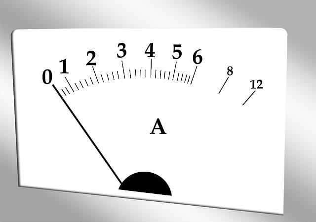
The measure of the strength of an electric current is the purpose of this instrument, the ammeter.
Note: The ammeter is always connected in series to the rest of the circuit (we will discuss series and a parallel circuit later in this article).
The concepts about electric current are incomplete without the discussion of conventional current and electron flow. It is time to discuss this topic now.
Conventional current and electron flow:
As discussed earlier, protons (positively charged particles) were discovered earlier than electrons (negatively charged particles).
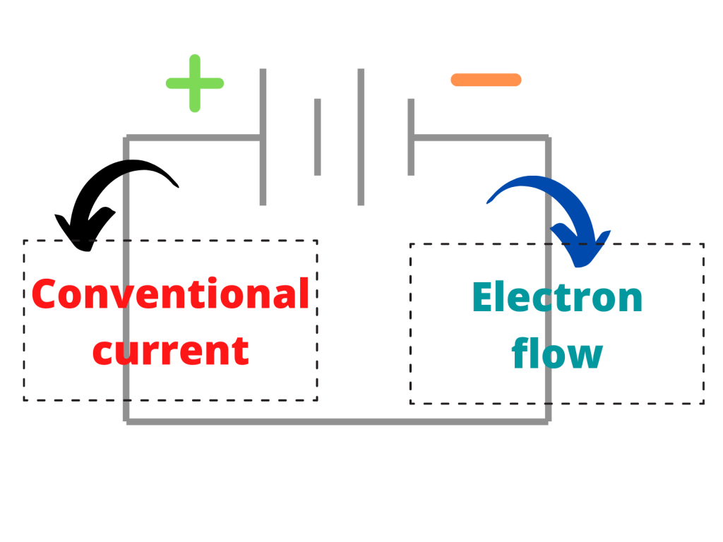
Therefore, the scientists believed that electric current was the flow of positive charges. This theory is referred to as the “conventional current”.
What is electron flow?
The scientists later discovered the movement of electrons from the negatively charged terminal to the positively charged terminal. This is known as the electron flow.
Why electrons move from negatively to a positively charged terminal? The reason is that the same charges repel each other and same is the case with electrons.
They repel each other causing them to move away from the negative terminal.
This was all about the definition of electric current and the terms related to it.
It is time to move towards other important terms such as the electromotive force (e.m.f) and potential difference.
Electromotive force (e.m.f):
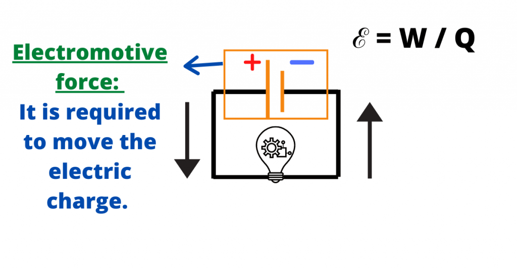
In simple words, the electromotive force is the force which is required to move the electric charge along a circuit.
The devices such as batteries and generators convert different forms of energy into electrical energy. This is known as the electromotive force.
To understand this, recall the working of a motor to pump water. The motor provides a force to move water along the pipes with a pump. You can refer to this force as electromotive force.
Read:
In Physics, the electromotive force is is the work done (energy provided) by a source (such as a battery or a generator) to drive a unit charge (Q) around a circuit.
In terms of formula, you can say that:
ℰ = W / Q
ℰ = Electromotive force (emf) in Volt
W = Work done (in Joule)
Q = Charge (in Coulomb)
The SI unit of electromotive force is Volt (V).
What is Volt? Let me tell you.
If a source does one Joule work to drive a charge of one Coulomb around a circuit then, it can be said that an electromotive force of one Volt is produced.
Note: The e.m.f is not same in series and parallel circuits.
The difference is that in a series circuit, the resultant e.m.f will be the sum of all e.m.f’s along the circuit.
For example, if e.m.f in one cell is 1 Volt and the e.m.f in the second cell is 1 Volt then, the total e.m.f will be 2 Volt.
In Parallel, if e.m.f in both cells is 1 Volt then, the resultant e.m.f will also be 1 Volt because, in a parallel circuit, the resultant e.m.f is equal to the e.m.f of one single cell.
I hope that this makes sense.
Potential difference:
Potential difference refers to the fact that electrical energy is converted into other forms of energy such as thermal energy.
In other words, potential difference is the difference in the amount of energy between two points in a circuit.
Note: The unit of electromotive force and the potential difference is the same but these two terms are different.
In terms of formula, potential difference is:
V = IR
V = Potential difference across the component (in Volt)
I = The current flowing through the circuit (in Ampere)
R = Resistance of the component (in Ohm)
It is to remember that potential difference is the product of current (I) and resistance (R).
This takes us to another very important topic which is about resistance, so let’s discuss the topic as well.
Resistance:
Resistance is the opposition that the electric current faces when it is moving across a component.
In Physics, resistance refers to the ratio between potential difference and the current flowing through a component (R = V / I).
It is to note that the higher the resistance, the less current will flow across a component. This is because the opposition to the current will be greater.
Similarly, the lower the resistance, the greater current will flow across a component. This is because the opposition to the current will be less.
The SI unit of resistance is Ohm. One ohm is the resistance when a one-volt potential difference is applied to drive one-ampere current across a component.
Resistors are the conductors that control the amount of current flowing through an electric component. The value of resistance in a fixed resistor is the same while in a variable resistor, the value of resistance can be changed.
The resistance of a conductor is dependent upon:
- Temperature
- Length
Resistance is directly proportional to length. This means that if the length is greater, the resistance (opposition) will also be greater (increase proportionally).
- The thickness or the cross-sectional area
Resistance is inversely proportional to the cross-sectional area. This means that if the thickness is greater, the resistance (opposition) will be less.
- Type of material
This takes us to another very important topic in this chapter which is about the ohm’s law and the ohmic and non-ohmic conductors.
If you are not familiar with these terms, do not worry. I will explain you everything you need to know about these terms.
Ohm’s Law:
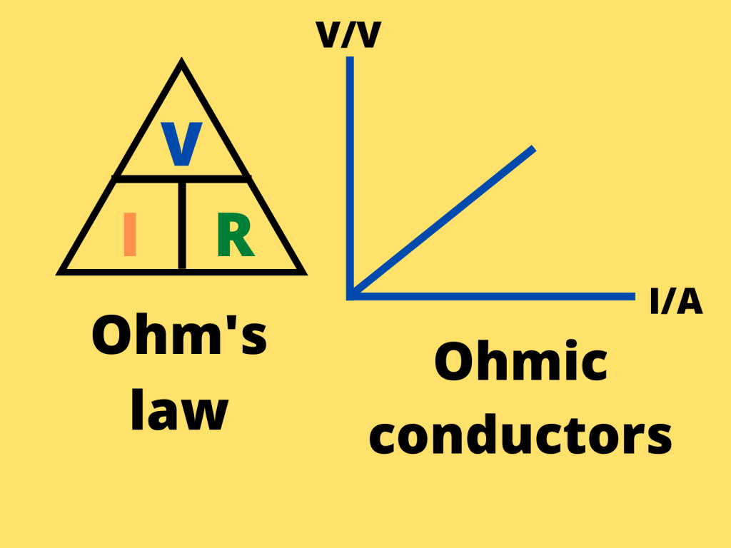
There is a relationship in physics which states that if the temperature is kept constant, the potential difference across a metallic conductor will be directly proportional to the current.
This relationship is known as the ohm’s law.
I ∝ V
I = Current
V = Potential difference
According to ohm’s law, resistance remains constant under steady physical conditions.
This law was proposed by a German scientist, Georg Ohm.
When studying about ohm’s law, we come across some important terms such as ohmic and non-ohmic conductors.
What does these terms mean? It is time to discuss them as well.
Ohmic and non-ohmic conductors
There are the conductors that obey (follow) the ohm’s law and their charactersticks are:
- In an I – V graph, there is a straight line passing through the origin
- The gradient is constant and which is equal to the inverse of the resistance of the conductor.
The conductors that follow the above-mentioned rules are known as ohmic conductors while those that do not are known as non-ohmic conductors.
The current flowing through the non-ohmic conductors is not directly proportional to the potential difference across the component.
Unlike ohmic conductors, the resistance can vary (recall that resistance is constant in ohmic conductors).
- Unlike ohmic conductors, the I – V graph of non-ohmic conductors does not show a straight line.
Therefore, the resistance is not constant.
You should also remember the relation between temperature and resistance. If the temperature increases, the resistance also increases.
This means that resistance and temperature and generally directly proportional.
As promised earlier, it is time to briefly discuss series and parallel circuit as well because your syllabus requires you to be familiar with these two terms.
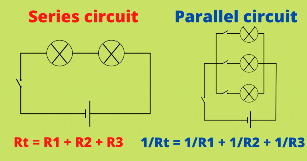
Series and parallel circuit:
In series circuit, there is only one path for the flow of current.
The components are connected in a line, end-to-end, to provide only one path for the flow of current (I).
The resistors in a series circuit are arranged in a chain and this is the reason why current flowing through each resistor is the same.
In a series circuit, you add all the resistances to find the total or resultant resistance. Therefore, the total resistance is greater than the greatest single resistance.
Let me explain this with the help of an example.
Let’s suppose that there are three resistors connected in series. Their resistance is as follows:
- Resistance 1 (R1) = 10 V
- Resistance 2 (R2) = 15 V
- Resistance 3 (R3) = 20 V
The total resistance will be 45 V (10 V + 15 V + 20 V) which is greater than the single largest resistance. Note that the single largest resistance, in this case, is 20 V.
In a parallel circuit, the potential difference across all ends is the same. The total current is the sum of all currents flowing through each individual component.
There are many paths that a current can take to flow through a component connected in parallel but, the voltage is the same across all paths of a parallel circuit.
In other words, components are connected across each other in a parallel circuit.
Conclusion:
With this, the article regarding current electricity has come to an end. I hope that all your questions have been answered and your queries have been cleared.
Thank You very much for reading and staying with me till the end. The topics discussed in this article are referred below so that you can consult them and review them.
- Conventional current
- Ohm’s law
- Series circuit
- Parallel circuit
- Electromotive force and potential difference
- Resistance
Share this post with your friends so that they can also revise this important topic which is in your O level syllabus.